Instructions of crack identification operation in PCAS
Automatic analysis of crack network
The identification and quantitative analysis of the crack network image is achieved by the following steps:
(1) Open the crack image and pop up the “Segmentation” dialog box. The program will automatically split the image to get the binary crack image, then click “OK” to return.
(2) If the edge of the crack is rough, click on “Closing (Smooth)” to smooth the edge of the crack. The radius of the smoothing element is 2 pixels (2-5 depending on the image size).
(3) Click “Auto analysis” to automatically clear the noise, repair the crack, and pop up the crack network block information table.
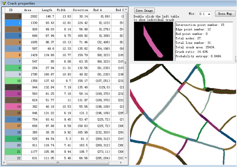
(4) Click the “Crack” tab, then click “Auto analysis (Crack)”, wait 10-30 seconds to get the center axis of the crack network, and then click “Crack property table” to pop up the crack geometry table.
Note: Click on “View image” in the program to zoom in and view the image. In the information table, you can click on the elements in the table to view the specific information of a single crack (as shown below).

Process crack network step by step
(1) Open the crack image and pop up the “Segmentation” window. The program automatically sets the gray threshold and converts the image into a binary image. Click “OK” to return to the binary image.
(2) Click “Closing (Smooth)” and “Element radius” is taken as 2.
(3) Click on “Recognize regions” and the program will automatically identify the blocks surrounded by the crack network.
(4) Click on “Enclose regions” to cut the small connections between the blocks.
(5) Click on “Black spots” to remove all black spots.
(6) Click “Convert to binary image” to convert the image into a binary image.
(7) Click on “Recognize regions” to get the new block.
(8) Click on “White spots” to remove white noise.
(9) Click on “Region property table” to pop up the window and display the geometry of the block.
(10) Go back to the main window and click on “Convert to binary image” to get the
ideal binary image.
(11) Click on the “Cracks” tab.
(12) Set the “Protect width” (usually the width of the crack) and click on “Skeletons” to get the crack skeleton.
(13) Click on “Pruning” to remove the small protrusions on the crack and obtain the central axis of the crack network.
(14) Click on “Crack property table” and the pop-up window displays the various geometric properties of the crack.
![0LLDNXW]00)05LDJ@Z9EE]N.jpg 0LLDNXW]00)05LDJ@Z9EE]N.jpg](http://matdem.com/upload/image/20171202/15122008746356077.jpg)
Note: In the “Segmentation” window above, click “Edit binary image” to pop up the “Image editor” window, and manually correct the binary image (below), such as clearing large spots.
![R@}G2W5[X]JO[JZ6T8~M81H.jpg R@}G2W5[X]JO[JZ6T8~M81H.jpg](http://matdem.com/upload/image/20171202/15122009437023634.jpg)
